Clustering - [BETA]
Writing of this tutorial is currently in progress. If you wish to follow this tutorial, please consider yourself a beta tester (and don’t hesitate to send us any improvement suggestions).
The following topics are covered in this tutorial:
- Reduction of actor firings in PiSDF graph to reduce mapping and scheduling time.
- Code generation for a distributed architecture using the hierarchical mapping approach.
Prerequisite:
Last update the 26.05.2020 - Tutorial created the 22.02.2020 by D. Gageot
Project setup
In addition to the default requirements (see Requirements for Running Tutorial Generated Code), please download the following files:
- Complete Sobel-Morpho Preesm Project
- YUV Sequence (7zip) (9 MB)
- DejaVu TTF Font (757KB)
- Automatic clustering workflow (6.45 KB)
- Manual clustering workflow (5.42 KB)
To set-up the clustering workflows, please download the two workflows above and insert them into the Workflows/ folder of the Sobel-Morpho project.
Clustering techniques
Why clustering a PiSDF graph?
Mapping and scheduling a Synchronous Dataflow Graph (SDFG) is a NP-complete problem. This means that the time required to map and schedule an input graph is exponential to its number of actor firings and cores. Methods such as hierarchical scheduling and hierarchical mapping are used to reduce the amount of data in input of these algorithms.
The hierarchical scheduling method consists of clustering actors in an SDFG to reduce the number of actor firings, then reducing mapping and scheduling time Actors contained in a dataflow cluster are sequentialized since the resulting cluster will be mapped on a single processing element.
The hierarchical mapping method is used with distributed architecture and aims to reduce the number of PEs of the targeted architecture by modeling only the cluster hierarchy in the System-Level Architecture (S-LAM). For example, the manycore processor Kalray MPPA Bostan is composed of 16 compute clusters of 16 PEs. It architecture model within PREESM only contains the cluster hierarchy. In combination with the hierarchical scheduling method, actor firings contained in a dataflow cluster are parallelized inside a compute cluster. The clustering technique used in PREESM is able to keep data parallelism over repeated actor firings in a dataflow cluster by using OpenMP.
In this tutorial, you will learn how to set up a workflow that features hierarchical scheduling and hierarchical mapping and apply it to the Sobel-Morpho project. We are going to cover three different usage:
- Hierarchical scheduling with manual and automatic partitioning,
- Hierarchical mapping on one compute cluster,
- Hierarchical mapping on multiple compute clusters.
Introduction to the clustering workflow
This section introduces the basic clustering workflow for both hierarchical scheduling and mapping. The workflow shown in the figure below has four components:
- Cluster Partitioner:
The Cluster Partitioner clusters automatically groups of actors in the input PiSDF graph. - Cluster Scheduler:
The Cluster Scheduler computes the schedule for each cluster founded by the cluster partitioner or specified by hand by the user. The resulting schedule is modeled with a Cluster Schedule (CS), an intermediate representation that describes the internal schedule of a dataflow cluster while keeping parallelism information. If the targeted architecture is represented with its cluster hierarchy but has only one compute cluster, for example a basic shared-memory x86 processor, the Cluster Scheduler can be configured to cluster the whole input graph so that all actor firings are contained in a dataflow cluster. - Mapping and scheduling:
It is the legacy mapping and scheduling workflow of PREESM. It chooses on which compute cluster to execute actor firings at coarse-grained level. - Code Generator:
The Code Generator generates code from both DAG and CSs. Since CSs contain parallelism information such as data parallelism, OpenMP pragmas are printed on top of for-loops.

Hierarchical scheduling
Manual partitioning
Manual partitioning of a PiSDF graph is used to force a specific PiSDF subgraph to be considered as a cluster. It might be needed when the automatic clustering isn’t able to cluster a group of actors that the developer wishes it to be. To do so, the developer has to set-up a proper PiSDF subgraph, add it to the top graph and set it cluster attribute to true. To practice, lets cluster actors Sobel, Dilation and Erosion together:
- Create a new .pi graph and named it
cluster.pi, - Duplicate
sobel_morpho.piand rename itsobel_morpho_clustered.pi, - Select actors Sobel, Dilation and Erosion in
sobel_morpho_clustered.piand copy them incluster.pi, - Create Config Input Interface for each parameter
sobelHeight,dilationHeight,erosionHeight,widthandwindowincluster.pithen connect them with the Dependency tool to actors of the cluster, - Create one Data Input Interface and one Data Output Interface in
cluster.pi, - Connect the Data Input Interface with the FIFO tool to Sobel and then Erosion to the Data Output Interface,
- Change type of new FIFOs from
voidtouchar, - Connect parameters to data port interfaces and set their firings as follow:
- data input interface:
sobelHeight*width, - data output interface:
(erosionHeight-2*window)*width.
- data input interface:
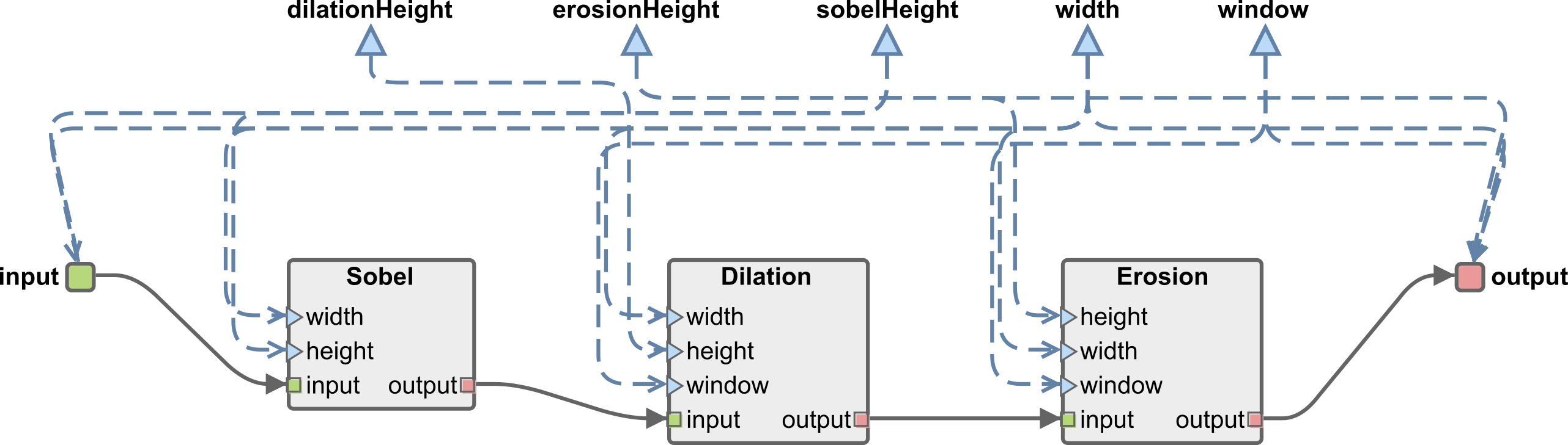
- As this point, your subgraph should look like this one:
- We need to specify to PREESM that this subgraph is a cluster. To do so, open
cluster.piwith Text Editor and add the attributecluster="true"in thegraphelement such as shown by the following figure:

- Delete Sobel, Dilation and Erosion actors from
sobel_morpho_clustered.piand replace them with a new actor called Cluster with a refinement tocluster.pi, - Set-up its ports rates and parameters,
- Connect Cluster to the output of Split and to the input of Display with the FIFO tool, don’t forget to change type of FIFOs.
- At this point, the top graph should look like this one:

Once application graphs are set-up, duplicate a 4 core x86 scenario and call it 4coreHierarchical.scenario.
Set the path of the top graph to sobel_morpho_clustered.pi.
Don’t forget to specify resource constraints afterwards.
In the worklow CodegenManualClustering, set the parameter Parallelism to False in the Cluster Scheduler task.
Indeed, dataflow clusters must not contain parallelism information since they are mapped on single PEs and not compute clusters in case of hierarchical scheduling.
Run the workflow on the scenario 4coreHierarchical.scenario.
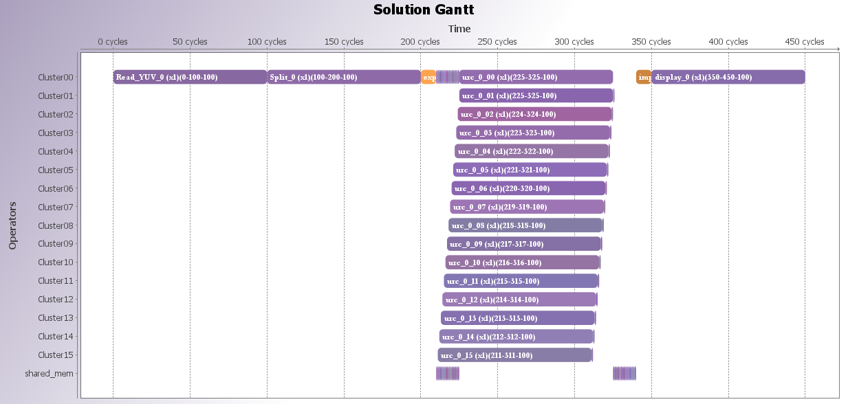
The resulting Gantt may involve firings of the cluster actor Cluster without any mention to Sobel, Dilation or Erosion.

These lines in the console show the internal schedule (represented with a CS) of the hand specified cluster (“*” symbol means sequential operator):
10:07:26 NOTICE: Workflow Step: 'Cluster Scheduler' (id 'cluster-scheduler'): Starting Execution of Cluster Scheduler Task
10:07:26 NOTICE: Scheduling clusters.
10:07:27 NOTICE: Schedule for Cluster:
10:07:27 NOTICE: Sobel*Dilation*Erosion
Every time a cluster actor is fired, a code scope is printed ine the generated code. For our example, here is the code generated for one firing of Cluster:
// Cluster: Cluster
// Schedule: Sobel*Dilation*Erosion
{
  uchar mem_Dilation_to_Erosion_0[26752]; //  size:= 26752*uchar
  uchar mem_Sobel_to_Dilation_1[28160]; //  size:= 28160*uchar
  sobel(352/*width*/, 82/*height*/, output_1__input__0, mem_Sobel_to_Dilation_1); // Sobel
  dilation(80/*height*/, 352/*width*/, 2/*window*/, mem_Sobel_to_Dilation_1, mem_Dilation_to_Erosion_0); // Dilation
  erosion(76/*height*/, 352/*width*/, 2/*window*/, mem_Dilation_to_Erosion_0, output__y_1__0); // Erosion
}
As you can see, it is cumbersome to manually cluster part of an existing graph. In the next section, the same group of actors will be clustered automatically with the Cluster Partitioner.
Warning: Do not use hierarchy and getter/setter inside a cluster, the Cluster Scheduler do not support them for the moment.
Automatic partitioning
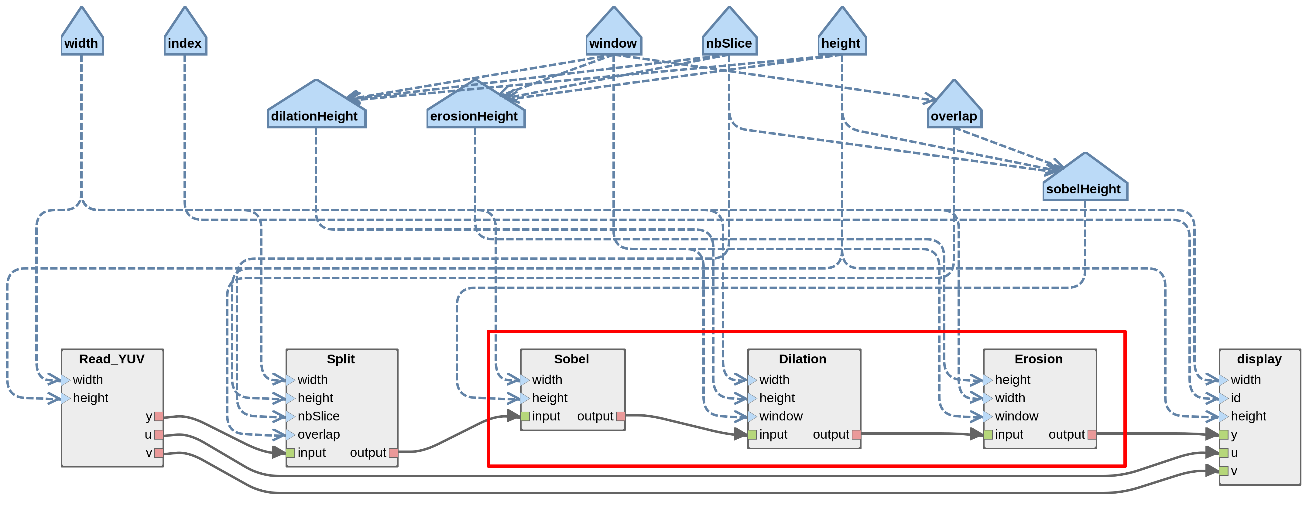
We have seen that manual clustering is cumbersome. In this section, we introduce the Cluster Partitioner task which clusters groups of actors that form Uniform Repetition Count (URC) chain. A URC is defined as a chain of actor in which all actors share the same repetition count without having any kind of internal state. Since actors are dependent of previous actor firings in the chain, no parallelism information is lost if the whole URC chain is clustered. For the moment, this is the only a pattern that is automatically partitioned by the Cluster Partitioner. In the example of Sobel-Morpho, actors Sobel, Dilation and Erosion form a URC chain (see the figure below). Their common repetition count is equal to the number of slices.
In the workflow CodegenAutomaticClustering.workflow, set the parameter Parallelism to False in the Cluster Scheduler task. Also, set the parameter Number of PEs in compute clusters to 1 in the Cluster Partitioner task. This parameter is used to balance firings of URC chain between coarse and fine-grained level, but since we target single PEs, we set this parameter to one. Run the workflow on the scenario 4core.scenario. The resulting Gantt may involve firings of the cluster actor urc_0 without any mention to Sobel, Dilation or Erosion, just like with the manual clustering procedure. This line in the console shows that the Cluster Partitioner has identified a URC chain in the graph:
10:04:07 NOTICE: Workflow Step: 'Cluster Partitioner' (id 'cluster-partitioner'): Starting Execution of Cluster Partitioner Task
10:04:07 NOTICE: urc_0: firings balanced by 1, leaving 256 firings at coarse-grained.
Warning: The Cluster Partitioner is aware to resource constraints. If you cannot get a URC chain clustered automatically, maybe actors of the chain do not have common resource constraints.
Hierarchical mapping
One compute cluster
In this section, we will generated code for a x86 platform consider to be one compute cluster. This idea is to entirely schedule a PiSDF graph with the Cluster Scheduler and exploit data parallelism sources with OpenMP. On a complex application, a speedup in mapping and scheduling time can be achieved. Open the workflow CodegenManualClustering.workflow and set parameters Parallelism to True and Target to Input graph in the Cluster Scheduler task. By doing so, the Cluster Scheduler will cluster the entire graph and represent it schedule with a CS which contain parallelism information. Run the workflow on the scenario 1core.scenario. The single core represent the compute cluster. As a result, the whole input graph has been scheduled, giving a complete schedule expression (4/ means four parallel firings):
11:00:04 NOTICE: Workflow Step: 'Cluster Scheduler' (id 'cluster-scheduler'): Starting Execution of Cluster Scheduler Task
11:00:04 NOTICE: Scheduling the input graph.
11:00:07 NOTICE: Schedule for cluster_0:
11:00:07 NOTICE: Read_YUV*Split*4/(Sobel*Dilation*Erosion)*display
Since OpenMP pragmas are printed in generated code, no pthread launches is used, otherwise OpenMP won’t be able to parallelize the firings of Sobel, Dilation and Erosion. The code scope generated for the cluster actor firing in generated/Core0.c shows that the for-loop containing function calls of Sobel, Dilation and Erosion has its four iterations parallelized with a OpenMP pragma.
// Cluster: cluster_0
// Schedule: Read_YUV*Split*4/(Sobel*Dilation*Erosion)*display
{
  uchar mem_Read_YUV_to_Split_0[101376]; //  size:= 101376*uchar
  uchar mem_Read_YUV_to_display_1[25344]; //  size:= 25344*uchar
  uchar mem_Read_YUV_to_display_2[25344]; //  size:= 25344*uchar
  uchar mem_Split_to_cluster_1_3[115456]; //  size:= 115456*uchar
  uchar mem_cluster_1_to_display_4[101376]; //  size:= 101376*uchar
  readYUV(352/*width*/, 288/*height*/, mem_Read_YUV_to_Split_0, mem_Read_YUV_to_display_1,
      mem_Read_YUV_to_display_2); // Read_YUV
  split(4/*nbSlice*/, 352/*width*/, 288/*height*/, 5/*overlap*/, mem_Read_YUV_to_Split_0, mem_Split_to_cluster_1_3); // Split
  // Begin the for loop
  {
    int index_cluster_1;
    #pragma omp parallel for private(index_cluster_1)
    for (index_cluster_1 = 0; index_cluster_1 < 4; index_cluster_1++) {
      // Cluster: cluster_1
      // Schedule: 4(Sobel*Dilation*Erosion)
      {
        uchar mem_Sobel_to_Dilation_0[28160]; //  size:= 28160*uchar
        uchar mem_Dilation_to_Erosion_1[26752]; //  size:= 26752*uchar
        sobel(352/*width*/, 82/*height*/, mem_Split_to_cluster_1_3 + index_cluster_1 * 28864,
            mem_Sobel_to_Dilation_0); // Sobel
        dilation(80/*height*/, 352/*width*/, 2/*window*/, mem_Sobel_to_Dilation_0, mem_Dilation_to_Erosion_1); // Dilation
        erosion(76/*height*/, 352/*width*/, 2/*window*/, mem_Dilation_to_Erosion_1,
            mem_cluster_1_to_display_4 + index_cluster_1 * 25344); // Erosion
      }
    }
  }
  yuvDisplay(0/*id*/, mem_cluster_1_to_display_4, mem_Read_YUV_to_display_1, mem_Read_YUV_to_display_2); // display
}
Multiple compute clusters
In this section, we will generate code for the Kalray MPPA Bostan by using the Cluster Partitioner task. The objective is to cluster the URC chain composed of Sobel, Dilation and Erosion and then apply variation on production and consumption rates of the subgraph to balance firings between coarse and fine-grained levels.
We may increase the number of slices to fit the number of PEs in the architecture. Set the nbSlices parameter to 256 in the Sobel-Morpho PiSDF graph. The video resolution may also be changed to not fit in the shared memory of each compute cluster, then set the width parameter to 400 and the height to 512 In the workflow CodegenAutomaticClustering.workflow, set the parameter Number of PEs in compute clusters to 16 in the Cluster Partitioner task. Be sure that the Cluster Scheduler is targeting clusters and that parallelism is enabled. Run the workflow on the scenario MPPA2.scenario. The resulting Gantt shows that there are only 16 firings of the actor urc_0 at coarse-grained since firings have been shared with the fine-grained level. We can see that fine-grained level obtained firings with the internal schedule of urc_0 which is equal to 16/(Sobel*Dilation*Erosion).