Parallelize an Application on a Multicore CPU
The following topics are covered in this tutorial:
- Implementation of a Sobel filter with Preesm
- C Code generation
- Parallelization for multi-threaded environment
Prerequisite:
Last update the 2025.12.04 - Tutorial created the 07.31.2013 by K. Desnos
Initial project setup
The first task of this tutorial consists of retrieving and compiling a sample Preesm project that will serve as a basis for the remainder of this tutorial. This first application simply consists of 2 actors and 3 parameters:
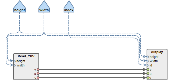
- Read_YUV: Actor that reads a YUV video frame by frame and outputs the three components separately.
- display: Actor that displays an YUV frame in an SDL window.
- height and width parameters correspond to the dimensions of the read and displayed video frames.
- index parameter is an integer referencing the display window. (can be used to enable several simultaneous windows).
Downloads
In addition to the default requirements (see Requirements for Running Tutorial Generated Code), download the following file:
- Preesm Sobel Project (28 KB)
Uncompress the preesm project in a directory named “org.ietr.preesm.sobel”.
Run Preesm Project
- Click on “File / Import …”, then “General / Existing Projects into Workspace” then locate and import the “org.ietr.preesm.sobel” project;
- Right-click on the workflow “/Workflows/Codegen.workflow” and select “Preesm > Run Workflow”;
- In the scenario selection wizard, select “/Scenarios/1core.scenario”;
- During its execution, the workflow will log information into the Console of Preesm. When running a workflow, you should always check this console for warnings and errors (or any other useful information).
The workflow execution generates intermediary dataflow graphs that can be found in the “/Algo/generated/” directory. The C code generated by the workflow is contained in the “/Code/generated/” directory.
Run the generated C Project
To compile and run the generated C code, simply use the CMake project of the /Code/ directory. We strongly advise you to generate the IDE projects and binaries in the /Code/bin directory so as not to mix the source code with OS/IDE specific files. In the /Code/ directory, batch scripts (*.bat and *.sh) are available to automatically create the appropriate folder and launch the CMake project generation for Windows users of Visual Studio 2022 (CMakeVS2022.bat) as well as for Linux GCC users (CMakeGCC.sh).
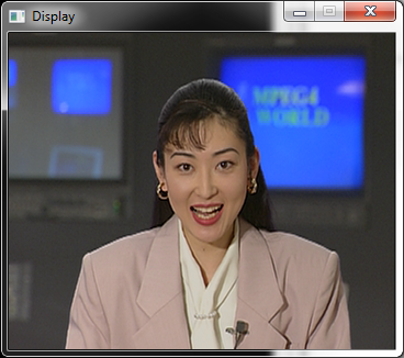
The following figure shows how the running application should look like. At this point, the application does not do any “real” computation on the image. The performance figure displayed in frames per second (fps) in the console should be noted, as it will be an upper bound to the performance of the developed video processing application. Indeed, since you will now add new actors to the dataflow graph, the amount of computation will increase and the application performance will decrease.
Sequential implementation of the Sobel filter
The Sobel filter is an image transformation widely used in image processing applications in order to detect the edges of a 2-dimensions picture. The application of this filter consists of convoluting the Y component of the original image with 2 matrices to obtain two intermediary images. These two images are then assembled to form the final image. More information on the Sobel filter can be found on Wikipedia.
Original C code
A C implementation of the Sobel filter is given hereafter:
void sobel(int width, int height, unsigned char *input, unsigned char *output) {
  int i,j;
  // Apply the filter
  for(j=1; j<height-1; j++){
    for(i=1; i<width-1; i++){
      int gx = -input[(j-1)*width + i-1] -2*input[ j*width + i-1] -input[(j+1)*width + i-1]
               +input[(j-1)*width + i+1] +2*input[ j*width + i+1] +input[(j+1)*width + i+1];
      int gy = -input[(j-1)*width + i-1] -2*input[(j-1)*width + i] -input[(j-1)*width + i+1]
               +input[(j+1)*width + i-1] +2*input[(j+1)*width + i] +input[(j+1)*width + i+1];
      output[j*width + i] = (abs(gx) + abs(gy))/8;
    }
  }
  // Fill the left and right sides
  for(j=0; j<height ; j++){
    output[j*width] = 0;
    output[(j+1)*width-1] = 0;
   }
}
The C file and its corresponding header file can be downloaded here. The C file and the header file should respectively be placed in “/Code/src/” and “/Code/include/”.
Preesm sequential Sobel
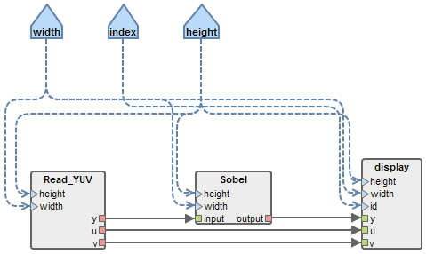
Add a new Sobel actor to the application graph. To do so:
- Double-click on “/Algo/top_display.diagram” to open the graph editor.
- Click on “Actor” in the palette (on the right side of the graph editor), then click in the graph to add a new Actor.
- In the “Create Actor” wizard, name the new actor “Sobel”.
- Delete the existing fifo between “y” ports of “Read_YUV” and “display” actors.
- Click on “Fifo” in the palette and click successively on the “y” ports of the “Read_YUV” and on the “Sobel” actor.
- Name “input” the “Sobel” input port for the new fifo.
- Repeat the last 2 steps to add another fifo between an “output” port of the “Sobel” actor and the “y” port of the display actor.
- Locate the “Properties” view of Preesm. (If the view is not visible, press F3 or go into “Menu bar > Window > Show View > Other…” and select “General > Properties”).
- Set the type of the newly created fifos to “uchar” (in the properties of the fifo, below the graph editor).
- Click on “Dependency” in the palette and click successively on the “width” parameter and the “Sobel” actor, name “width” the new configuration input port.
- Add another dependency between the “height” parameter and the “Sobel” actor.
- In the graph editor, select the fifo between actors “Read_YUV” and “Sobel”.
- In the “Properties” view, set the expressions associated to the source and target ports to: “height*width”.
- Repeat the last two steps for the fifo between actors “Sobel” and “display”.
- Drag-and-drop the “sobel.h” file from the “Project Explorer” on the “Sobel” actor in the graph.
- In the dialog, choose a prototype for the loop function (the function called at each execution of the sobel actor), select the only one proposed (named sobel).
- When asked to select an init function, click “Cancel”. (this function is optional and in the case of the sobel actor, unnecessary).
- Save the diagram.
- Open the “/Scenarios/1core.scenario” by double-clicking on it in the “Project Explorer”.
- In the “Constraints” tab, select the “Core0” operator and tick the “Sobel” box to allow the Sobel actor to execute on this core.
- Save the scenario.
- Execute the workflow. (Don’t forget to check the Console for errors and warnings.)
Run the sequential Sobel
The objective of this step is to confirm the correct behavior of the filter sequential implementation before parallelizing and optimizing it. After the workflow has completed its execution, recompile the application and run it.
The performance obtained with the sequential implementation will serve as a comparison point to measure the benefits of future optimizations. To run the application, simply follow the steps presented above.
If errors have occured in Preesm, they appear in red in the Console. In case the code has not been correctly generated, you can check the Preesm console.
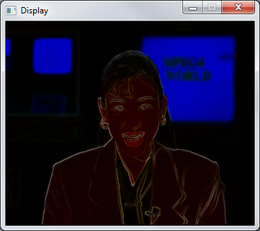
The following figure shows how the running application should look like.
Exposing Parallelism
The objective of this section is to modify the original Sobel application so as to expose a parameterizable degree of data parallelism. The basic idea behind this modification is to split the original image into slices that can be processed in parallel.

Split/Merge Actors
The computation of the Sobel filter involves the convolution of the image with 3x3 matrices. This operation implies that the computation of the nth line of pixels of the output image requires an access to the (n-1)th and (n+1)th lines of pixel of the input image. Consequently, the Split actor will produce slices with 2 extra lines of pixel: the last line from the previous slice and the first line of the next slice. A C implementation of the Split actor is given hereafter:
void split(int nbSlice, int width, int height, unsigned char *input, unsigned char *output){
  int i,j;
  int sliceSize = width*height/nbSlice;
  // Fill first and last line with 0
  memset(output,0,width);
  // First Slice
  memcpy(output+width, input, sliceSize);
  // Copy next line if several slice
  if (nbSlice > 1){
    memcpy(output + width + sliceSize , input + sliceSize, width);
  }
  // Slice other than first and last
  for(i=1; i<nbSlice-1; i++){
    int destIndex = i*(sliceSize+2*width);
    memcpy(output + destIndex, input+i*sliceSize-width, sliceSize+2*width);
  }
  // Last Slice
  i = nbSlice-1;
  if(nbSlice > 1){
    // we have i = nbSlice -1;
     int destIndex = i*(sliceSize+2*width);
    memcpy(output + destIndex, input+i*sliceSize-width, sliceSize+width);
  }
  // Last line
  memset(output + (height+nbSlice*2-1)*width,0,width);
}
Hereafter is the C implementation of the Merge actor whose purpose is to assemble the processed slices into the output image.
void merge(int nbSlice, int width, int height, unsigned char *input, unsigned char *output){
  int i;
  int sliceSize = width*height/nbSlice;
  // Copy the slice content except the first and last lines
  for(i = 0; i< nbSlice; i++){
    int idx = i*(sliceSize+2*width);
    memcpy(output+i*sliceSize, input+idx+width, sliceSize);
  }
}
In addition to the “input” and “output” pointers, those two actors receive 3 parameters:
- width and height: the dimensions of the sliced image
- nbSlice: the number of slices created/assembled by the actors. It is the developper responsibility to ensure that height is a multiple of nbSlice.
The C and header files corresponding to the Split and Merge actors can be downloaded [here]. Uncompress them in the “include” and “src” directories of your project.
Preesm parameterizable parallel implementation
Following the same steps as those given for creating the Sobel actor, add the “Split” and “Merge actors and the “nbSlice” parameter to the graph and connect them like shown on the following figure. Set the default value of the “nbSlice” parameter to 8 (edit the Expression field in the “Properties” view of the parameter).
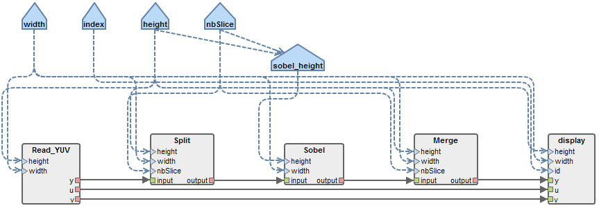
Since the Sobel actor will now receive slices of images rather entire images, we must give it the size of the slices as a parameter, not the size of the entire images. In order to do so, add a “sobel_height” parameter to the graph. Remove the dependency between the “height” parameter and the “Sobel” actor and replace it by three dependencies:
- one between “height” and “sobel_height”;
- one between “nbSlice” and “sobel_height”;
- and one between “sobel_height” and the “height” input port of the “Sobel” actor.
In the “Properties” view of the new parameter, enter the following expression: height/nbSlice+2.
Set the data type of all new FIFOs to “uchar”, then, define the following production and consumption rates for the new FIFOs of the graph.
| FIFO | Source Production | Target Consumption |
|---|---|---|
| read_YUV → Split | height * width | height * width |
| Split → Sobel | nbSlice * width * (height/nbSlice+2) | height * width |
| Sobel → Merge | height * width | nbSlice * width * (height/nbSlice+2) |
| Merge → display | height * width | height * width |
Before executing the workflow, you must:
- Associate the Split and Merge actors respectively with the loop function prototypes “split” and “merge” from the “/Code/include/splitMerge.h” file (still no init function there).
- Update the scenario to allow the execution of the new actors on “Core0”.
Exposed parallelism
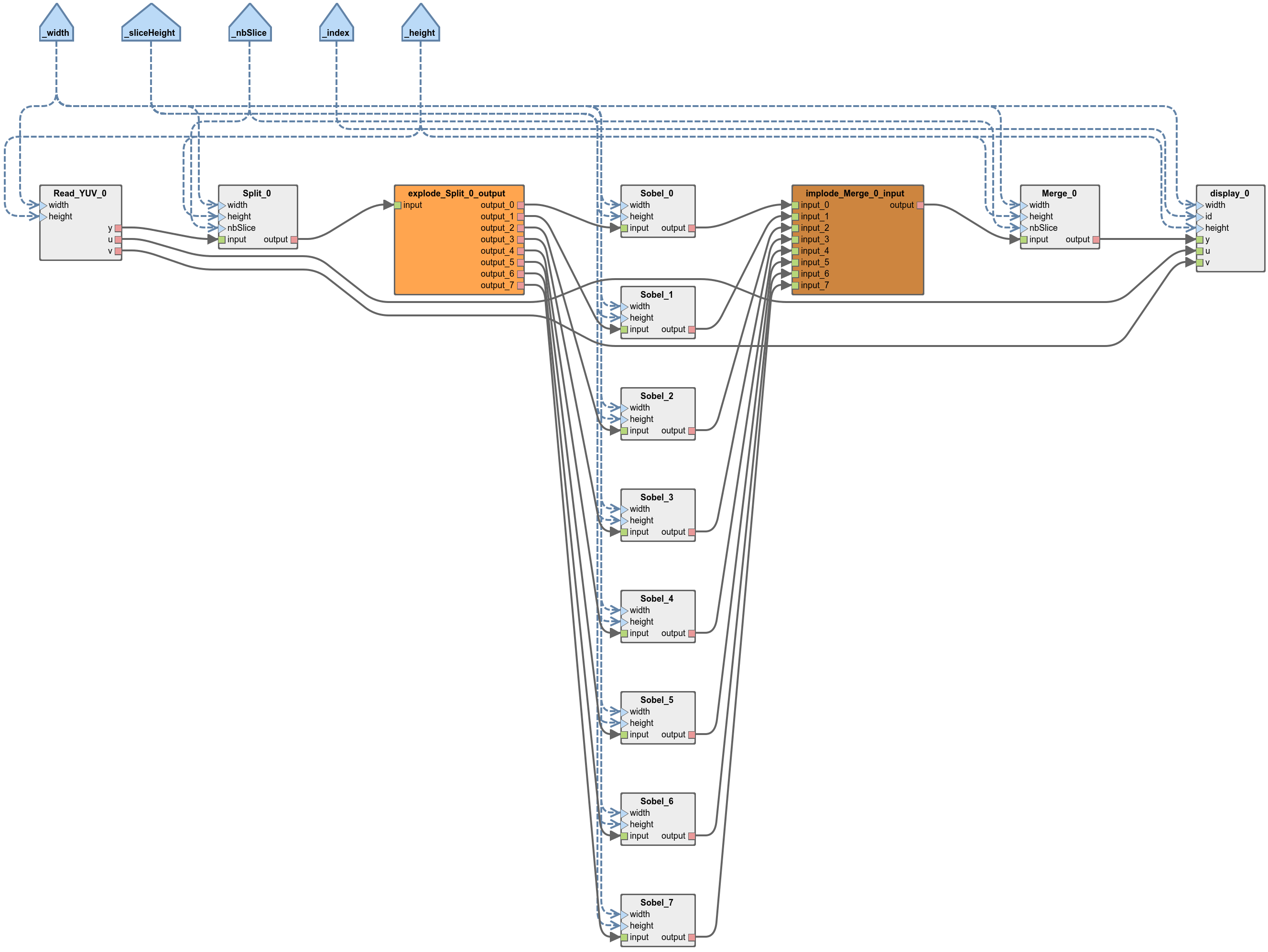
After executing the workflow on the mono-core scenario, locate the graph generated in “/Algo/generated/srdag/top_display.pi” and generate its diagram (right click / Preesm / Generate .diagram). This graph results from the transformation of the input PiSDF graph into an equivalent Single-Rate Directed Acyclic Graph (SRDAG) where each edge has equal production and consumption rates. As expected, this graph reveals 8 duplicates of the Sobel actor, each responsible for the processing of one of the slices.
Before proceeding to the next step, we strongly advise you to compile and run the application on 1 core. Even though a monocore execution will not benefit from the exposed parallelism, this step is often necessary to ensure the correct functionnal behavior of the application. Indeed, once parallelized on multiple threads/cores, the debugging task often becomes more complex and tiresome.
To compile the application, simply follow the steps presented above.
Multicore/Multithreaded execution
In this section, we are going to define a new architecture model and a new scenario in Preesm to exploit the application parallelism revealed after exposing the parallelism.
Multicore architecture model
In order to exploit the parallelism of the application, a new multicore architecture must be created. In Preesm, the System-Level Architecture (S-LAM) is used to model heterogeneous multiprocessor architecture with a high level of abstraction. This architecture model is used during the workflow execution to map and schedule the actors on the processing elements of the architecture and to route the inter-core communications. More information on the S-LAM model can be found in this paper.
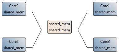
To create a new multicore achitecture model similar to the one in the figure, follow the following steps:
- In the “Project Explorer”, create a copy of “/Archi/1CoreX86.slam” and name it “4CoreX86.slam”
- Double-click on the new “4CoreX86.slam” to open it with the S-LAM Editor.
- Copy/Paste the “Core0” processing element 3 times. Name the new cores “Core1” to “Core3”.
- For each new processing element, in the “Basic” tab of the “Properties” pannel, and set the hardware ID accordingly to the number of the Core, from 1 to 3.
- Using the “undirectedDataLink” from the Palette, add connections between the “shared_mem” and the 3 new cores. Name all ports “shared_mem”.
You can use these steps to add any number of processing elements to your architecture to best reflect the number of core of your CPU. Note that one thread will be generated per core of the architecture model where some actors are mapped.
Generation of a multicore schedule
Before generating a multicore schedule, you need to create a new scenario that will associate the Sobel algorithm with the new 4Core architecture. To do so:
- In the “Project Explorer”, create a copy of “/Scenarios/1core.scenario” and name it “4core.scenario”.
- Double-click on the new “4core.scenario” to open it with the Scenario Editor.
- In the “Overview” tab, set the “Architecture file path” to “/Archi/4CoreX86.slam”.
- Save the scenario, close it and reopen it to take the new architecture into account in the editor.
- In the “Constraints” tab, allow the execution of all actors on all cores of the architecture (except read and display actors)
- Note: SDL2 is NOT thread safe. Make sure all read/display operations of your Preesm applications are always mapped on the same Core.
- In the “Simulation” tab, allow the execution of the broadcast/implode/explode actors on all cores.
- Save the updated scenario.
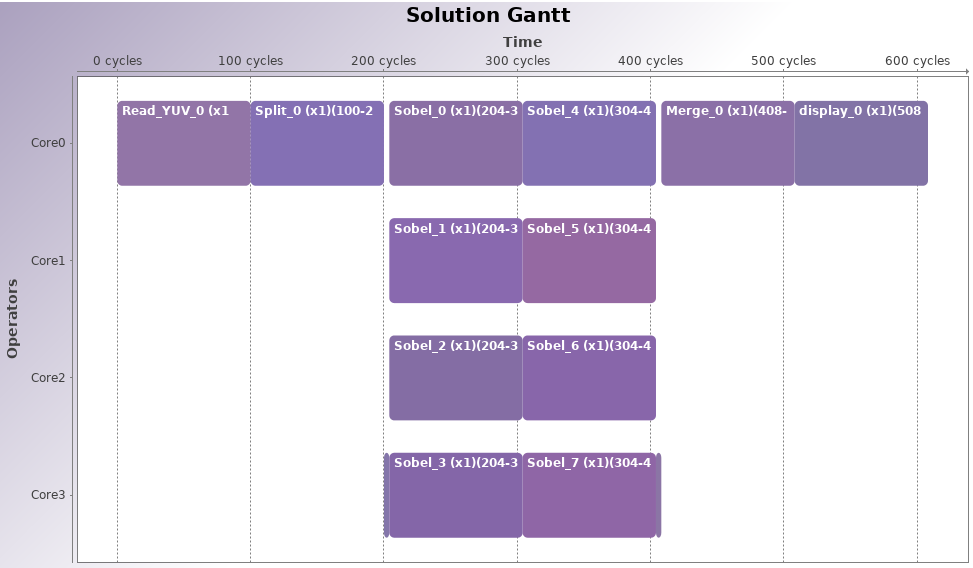
You can now run the “Codegen.workflow” with the new scenario. The generated schedule should make use of the 4 cores, as displayed in the produced Gantt graph.
Run the multithread code
When running the program, an fps counter is displayed (in the console and in the window). Using this indication, it is possible to measure the performance gain obtained when using multiple threads. For example, on an quad-core Intel Xeon CPU clocked at 3.10GHz, we observed a speedup of 2.67 (from ~375fps to ~1000fps) on a 352x288 image.
In order to have realistic timings in the Gantt chart, actor timings should be entered in the scenario. Actor timings must be measured by execution profiling.
The final project resulting from all the modifications presented in this tutorial is available here. (Note that the external libraries, the YUV sequence, the font and the generated C code are not included).
You can continue the tutorials by trying Tutorial 3: Code Generation for Multicore DSP.
Appendix: Change the input resolution
This section details the changes needed in order to run the Sobel application with YUV sequences of different resolution and length (such as the ones available [here]).
- In the application graph editor.
- Set the new values of width and height, and check that nbSlice is a multiple of height.
- Save the graph modifications and run the workflows.
- In “/Code/include/yuvRead.h”, set the pre-processor variable
NB_FRAMEto the number of frames of your sequence. You can also change the path to your YUV sequence in this file. Note that in the current implementation, theRead_YUVactor will not work for a large number of HD frames because of an overflow of the file pointer. - In “/Code/include/displayYUV.h”, set the pre-processor variable
DISPLAY_Wto<your video width>*NB_DISPLAYandDISPLAY_Hto your video height.