Code Generation for Multicore DSP
The following topics are covered in this tutorial:
- C Code and Instrumented C code generation
- Generation of cache coherent code
- Execution on a Multicore C6x DSP (EVM6678)
- Performance optimization of the application
Prerequisite:
Tutorial created the 10.14.2013 by K. Desnos
Project setup
In addition to the default requirements (see Requirements for Running Tutorial Generated Code), download the following files:
- Complete Sobel Preesm Project
- YUV Sequence (7zip) (9 MB)
- DejaVu TTF Font (757KB)
- A TMS320C6678 Evaluation Module (EVM)
- Code Composer Studio (CCS) v5.2.1 with MCSDK 2.x
⚠ Linux and Windows users: CCS versions 5.3 and greater for Linux and Windows do not support the installation of necessary plugins (BIOS MCSDK 2.x) for the use of Keystone I multi-core processors. We thus highly recommend to use a CSS version 5.2.1 and the offline installer. More information on MCSDK versions can be found here. Please read the CCS Setup page for detailed information about the installation and configuration.
The starting point of this tutorial is the Preesm project obtained as a result of the Parallelize an Application on a Multicore CPU tutorial.
Note: The supplied project has been designed and tested only with the TMDSEVM6678L EVM. However, we see no obvious reason why this project should not work with other Multicore DSPs from TI, provided that appropriate settings are made in the CCS project.
Preesm Code Generation for DSP
To begin this tutorial, open your own copy of the Sobel project in Preesm or simply unzip and import in Preesm the downloaded project. This project contains an implementation of the Sobel filter application obtained as a result of the Parallelize an Application on a Multicore CPU tutorial). The project modifications needed to generate code for multicore DSP from Preesm are presented in this section.
Definition of the Target Architecture
In the “Package Explorer” of Preesm, open the /Archi/ directory and create a copy of the “4CoreX86.slam” architecture named “8CoreC6678.slam”. Open the editor for the newly created architecture. Add 4 new cores to the architecture and name them Core4 to Core7)
For each of the 8 cores, open the “Properties” view and change the value of the “definition” attribute from “x86” do “c6678”. The “definition” attribute of the cores of the architecture is used during the workflow execution to generate adequate code for the specified targets. Save the S-LAM model and close the architecture editor.
Scenario Creation
In the “Package Explorer” of Preesm, create a new directory /CodeC6678/ and create a subdirectory named “generated”. Follow the following steps to configure a new scenario:
- In /Scenario/, create a copy of the “4core.scenario”. Name it “8coreC6678.scenario” and open it with the scenario editor.
- In the “Overview” tab, set the path to the “8coreC6678.slam” architecture, save, close and re-open the scenario editor to validate this change.
- In the “Constraints” tab, allow the execution of all actors on all 8 cores of the architecture.
- In the “Timings” tab, set the “memcopy speed” (scroll-down to make it appear) for c6678 cores with:
memcpySetupTime:=1andmemcpySpeed:=20000. (These values do not represent the reality but we need to set them to prevent the memcpy speed from dominating the simulation cost.). - In the “Simulation” tab, allow the execution of broadcast/explode/implode on all 8 cores.
- In the “Codegen” tab, set the code generation directory to “/CodeC6678/generated”.
- Save and close the scenario.
Code generation
You are now all set to generate code for the multicore DSP. To do so, simply launch the Codegen.workflow on the newly created scenario.
Code Composer Studio Project
In this section, we will guide you through the creation and configuration of the CCS project needed to compile and run the generated code. As CCS is an Eclipse-based tool, the behavior of CCS projects is equivalent to the one of Preesm projects.
Platform definition
The code generated by Preesm for multicore DSP relies on the definition of a custom target platform in CCS. This platform is used to specify the memory regions in which the code and data will be stored when running an application on the EVM. To create a custom platform:
- Create a subdirectory “/Code6678/package”.
- In Code Composer Studio (CCS), open the “Debug Perspective” (in “Menu Bar->Windows->Open perspective”).
- Open the Platform creation wizard by clicking on “Menu Bar->Tools->RTSC Tools->Platform->New”
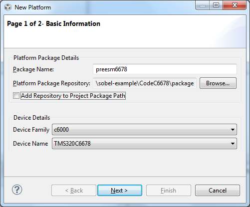
- In the wizard, name your platform “preesm6678” and set its repository to the “/package” directory (that would look like ${PREESM_Workspace}/org.ietr.preesm.sobel/CodeC6678/package). Do not check the “Add repository to Project Package Path” box.
- In the “Device Details” box, set the “Device Family” to “c6000” and the “Device Name” to “TMS320C6678”. Click on Next.
- Click on the “Import…” button, select “ti.platforms.evm6678” in the list and click on “OK”. In the confirmation dialog box, click on “Yes”.
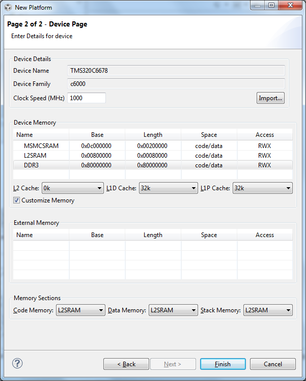
- In the platform editor, replace the memory configuration with the following memory ranges:
| Name | Base | Length | Space | Access |
|---|---|---|---|---|
| MSMCSRAM | 0x0c000000 | 0x00200000 | code/data | RWX |
| L2SRAM | 0x00800000 | 0x00080000 | code/data | RWX |
| DDR3 | 0x80000000 | 0x20000000 | code/data | RWX |
- Leave the cache configuration as it is and set the L2SRAM to store the Code, the Data and the Stack Memory. Click on “Finish”. (Make sure that the wizard looks exactly like the following screenshot before clicking on “Finish”.)
Project Creation
The following steps will guide you through the creation and the configuration of the CCS project:
- Go back in the “CCS Edit” perspective (in “Menu Bar->Windows->Open perspective”).
- Open the CCS Project creation wizard by clicking on “Menu Bar->File->New->CCS Project”.
- Name your project “sobel-6678” and set its location to your “/Code6678/” directory (again, if you use different workspaces, it would look like ${PREESM_Workspace}/org.ietr.preesm.sobel/CodeC6678/).
- In the “Device” box, set “Family” to C6000, “Variant” to TMS320C6678 and “Connection” to “Texas Instrument XDS100v1 USB Emulator”.
- In the “Project templates and examples” box, select “Empty RTSC Project” and click on Next.
- In the new page, click on the “Add…” button. In the opened dialog box, browse to your “/Code6678/package/” directory and click on “OK”.
- Back in the “RTSC Configuration Settings”, select “preesm6678” in the “Platform” list. Click on Finish.
- Open the properties of your project, go in the “General” tab in the “RTSC” sub-tab. Scroll down in “Products and Repositories” to “Other Repositories” and replace the absolute path to your package with the following value “${workspace_loc:/${ProjName}/package}”. This step is important to ensure the portability of your CCS Project independently from your personal directory organization.
If the “Build Automatically” option of CCS is activated, the compilation of your project will launch automatically but will encounter errors. The following steps will help you solve this issue)
- In the “Project Explorer”, right-click on the “sobel-6678/package” directory and select “Resource Configurations->Exclude from Build…”. In the wizard, exclude this directory from all compilation profiles.
- In the “Project Explorer”, create two new directories in your project path: “src” and “include”.
- Open the properties of your project and open the “Build/C6000 Compiler/Include Options” tab. Add two new directories to the “#include search path”: ”${workspace_loc:/${ProjName}/include}” and ”${CCS_INSTALL_ROOT}/../pdk_C6678_1_1_2_6/packages”. Make sure the path corresponds to the version of the PDK installed on your computer. To know the version of the PDK installed on your computer, you can go to “Window > Preferences > Code Composer Studio > RTSC > Products” and scroll down to “MCSDK PDK TMS320C6678”.
- Select the “Release” configuration in the properties editor and repeat these 3 steps to complete the configuration.
To compile the project, you now need to add to your project the source code that implements the communication and the synchronization primitives used in the generated code as well as the actor code. A zip file containing all necessary files is available [here]. This file should be merged with the “/Code6678/” directory.
Here is a short description of some of the files contained in the archive:
- modelPreesm.cfg: This RTSC configuration file is used to select and configure different modules used by Sys/Bios when running the application. In particular, the entry point of the program is declared in this file (i.e. the function called when a DSP calls BIOS_start()). The sections within which data can be allocated using a
#pragma DATA_SECTIONdirective are also defined in this file. - /include/cores.h: This file contains the definition of preprocessing variables that can be used to modify the behavior of the compiled code. For example, the COREx variables provide a convenient way to remove the declaration of a core that does not run any actor.
- /src/c6678.h: This header file contains the preprocessing #include directives for all header files containing prototypes of the actor functions.
- /src/main.c: The main program ensures that each of the 8 DSP Cores of the EVM executes the right code.
After the archive is unzipped, refresh the CCS Workspace and compile the project. At this point, the compilation should be successful.
Execution of the Sobel filter on an EVMC6678
After building the CCS project successfully, this section will show you how to load your application on the 8 cores of the DSP and how to check that the application works properly.
Loading the application on the EVM
Before loading the application on the EVM, we are going to configure the project to automate the tedious and repetitive task of loading the GEL files on each core of the EVM. To do so:
- In the “Project Explorer”, double click on the “/sobel-6678/TMS320C6678.ccxml” (or “/sobel-6678/targetConfigs/TMS320C6678.ccxml”) to open the associated editor.
- Open the “Advanced” tab of the editor.
- In the left part of this tab, select the “C66xx_0” element.
- In the right part of the tab, set the “initialization script” to the GEL file associated to your EVM. For the 6678, the path should be something like:
..\..\emulation\boards\evmc6678l\gel\evmc6678l.gelorC:\ti\ccsv5\ccs_base\emulation\boards\evmc6678l\gel\evmc6678l.gel. - Repeat the last two steps for the 7 remaining cores.
- Save and close the editor.
Before connecting your EVM to your computer and plugging its power supply in, make sure that your EVM is in “No Boot” mode. To do so, simply set the switches of the EVM6678 as follows: (cf. here for more information)
| DIP SW3 | DIP SW4 | DIP SW5 | DIP SW6 |
|---|---|---|---|
| off, on, on, on | on, on, on, on | on, on, on, on | on, on, on, on |
Connect your board, first to the PC USB, then to the power supply.
Back in CCS, open the “Target Configuration” view by clicking on “Menu Bar->Windows->Show View->Target Configuration”. In the “Target Configuration” view, right click on the ccxml file in “Projects/sobel-6678/” and select: “Launch Selected Configuration”. The CCS Debug perspective should open automatically.
To load the application on the EVM:
- In the “Debug” tab in top-left corner of the CCS Debug perspective, select the 8 cores of the architecture.
- Right-click on the selected cores and select “Group Core(s)”.
- Right-click on “Group 1” and select “Connect Target”. This will connect CCS to the 8 cores of the architecture and launch automatically the “Global Default Setup” script (from the GEL file) for each core. It may happen that the connection fails; in such case, unplug and reset the EVM and restart CCS and go back to step 1.
- Once all cores are connected, open the “Load Program wizard” by clicking on “Menu Bar->Run->Load->Load Program…”.
- In the wizard, click on the “Browse Project” button and select the “/sobel-c6678/Debug/sobel-6678.out” binary.
- Click on OK twice and wait for the completion of the loading process which may last a few tens of seconds… per core.
- Once all cores are loaded, click on the play button to launch the execution. When running, the application will print a number of FPS in the console.
Load the video in memory
In the map file generated next to the program (back in the “CCS Edit” perspective, in the “/sobel-6678/Debug/” directory), check where in memory is allocated the section “.myInputVideoMem”. It is certainly at the beginning of DDR, thus 0x80000000. In this section, we want to load the video. This section is defined as “NOINIT” in the SYS/BIOS cfg file so it will not be erased if you reload the code.
A program to convert the YUV video into a .dat hexadecimal file compatible with CCS is provided as static binaries for [win64] and [linux64])) The program is named yuv2dat. To use this program, launch the executable in a command window; this will tell you the required parameters to convert a *.yuv file. Set the number of frame to convert to 10 (“-f=10”). If you want a different value, you will need to change the pre-processing variable NB_FRAMES in the yuvRead.h file of your CCS project. Once you converted your input video, you can load the dat file in the DSP memory. To do so,
- Pause all executions in the debugger perspective.
- Select one of the cores in the in “Debug” tab.
- Open the Load memory wizard by clicking on “Menu Bar -> Debug -> Tools -> Load Memory”.
- In the opened wizard, select your *.dat file.
- Check the box to use the header information contained in the file.
- Click on Next.
- In the new page, set the address according to you observation of the *.map file. The Length of memory to load should be automatically read from the *.dat file.
- Click on “Finish”
- The load may take a few minutes.
In order to check that the video was correctly loaded, you can use the CCS “Image Analyzer”. Open the “Image Analyzer” by clicking on “Menu Bar->Tools->Image Analyzer”) Open the “Properties” view and set the properties as follows (starting with the image format):
| Property | Value |
|---|---|
| Image format | YUV |
| Number of pixels per line | 352 |
| Number of lines | 288 |
| Data format | Planar |
| Tiled | |
| Resolution | 4:2:0 |
| Y Pixel stride | 1 |
| Y mask | 0xFF |
| Y Line stride | 352 |
| U Pixel stride | 1 |
| U mask | 0xFF |
| U Line stride | 176 |
| V Pixel stride | 1 |
| V mask | 0xFF |
| V Line stride | 176 |
| Alpha Pixel stride | 0 |
| Alpha mask | 0x00000000 |
| Alpha Line stride | 0 |
| Image source | Connected Device |
| Y Start address | 0x80000000 |
| Read data as | 8 bit data |
Back to the Image tab, click on the Refresh button. You should now see an image from the video you loaded on the board.
Check the application functionality
The number of FPS displayed in the console when running the application is not a very convincing way to prove the correct operating of the Sobel application. The following steps will help you visualize the result of the Sobel application from the memory of the DSP.
- With the “Group 1” selected in the Debug tab, click on the Pause button to halt the execution of the 8 cores. (It is mandatory to stop the execution of a core before adding a new breakpoints.)
- In the “CCS Edit” perspective, open the “sobel-6678/src/yuvDisplay.c” file.
- Double-click in the margin next to the yuvDisplay(…) function to add a breakpoint.
- Go back to the “CCS Debug” perspective and resume the execution of the 8 cores.
- Wait until one of the 8 cores reaches the breakpoint (less than a second). If you have pipelined your application, resume the execution of the 8 cores several times (equal to the size of your pipeline). Select this core in the Debug tab.
- Open the “Image Analyzer” by clicking on “Menu Bar->Tools->Image Analyzer”) Also open the “Properties” view and place it side by side with the Image Analyzer.
- Set the properties as follows:
| Property | Value |
|---|---|
| Image format | RGB |
| Number of pixels per line | 352 |
| Number of lines | 288 |
| Data format | packed |
| Pixel stride | 1 |
| Red/Green/Blue mask | 0xFF |
| Alpha mask | 0x00 |
| Line stride | 352 |
| Image source | Connected Device |
| Start address | y |
| Read data as | 8 bit data |
- The setting displays the image in monochrome by using the same memory as R, G and B input. In the “Image” view, click on the “refresh” button. The filtered Akiyo frame should appear in the image view.
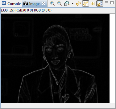
It sometimes happens that only white noise appears in the image view. This issue usually arises when something went wrong during the loading process. The best way to solve this issue seems to be to reload the binary on the EVM and re-launch the execution.
Instrumented C Code Generation, Execution and Analysis
Similarly to what is presented in the Automated Measurement of Actor Execution Time tutorial for CPU, it is possible to print instrumented code for DSPs. To do so:
- Re-open the Sobel project in Preesm and follow the steps of the CPU tutorial. In the last step, you can run the workflow on the existing “8coreC6678.scenario”.
- Following the instruction presented earlier in this tutorial, compile, load, and run the generated code. If the CCS project is located as advised in the subdirectory “CodeC6678” of your Preesm project, then a simple refresh, rebuild and reload of your CCS project will suffice.
- Execute the instrumented code for a few seconds. At the end of each iteration, statistics on the execution time of all actors will be printed in the console.
- Open with your favorite notepad the “/CodeC6678/generated/analysis.csv”. Copy the content of the console and paste it at the end of the csv file.
- Using a “Search and replace” wizard, delete all occurrences of “[C66xx_?] “. Manually remove the second line of the console (which displays a number of fps).
- Do not forget to adapt the decimal separator and the formula to your spreadsheet editor language.
- Open the spreadsheet to see the results.
You now have all the information you need to update the “Timing” tab of the Preesm scenario. Keep in mind that this method is experimental and the precision of the measured execution time might not be optimal. Moreover, the overhead induced by inserting instrumentation calls into the generated code has not been evaluated. Finally, using profiling tools from CCS might be a good idea. (Feel free to contact us if you want to help us improve this tutorial by using such techniques).
Generation of Cache Coherent Code
Despite the use of the 8 cores of the c6678, the performances obtained are still quite poor (~34fps in debug and ~50fps in release). The main reason for these bad performances is the memory allocation scheme used in the generated project. Indeed, the allocation scheme used in this project consists of mapping all the buffers used to transmit data from an actor to the next in the DDR3 memory. Because the DD3 memory is an external memory, memory accesses to data stored in this memory considerably slow down the execution of the program. To solve this issue, we are going to activate the DSP cache.
Activate the L1 Cache
Each one of the 8 cores of the EVM possesses a private L1 cache of 32kB. To activate this cache, simply follow these steps:
- Open “include/cache.h” file in CCS.
- Set the CACHEABLE pre-processing variable to 1.
- Make sure that
#define L1is not commented. - Rebuild your project.
Then, simply load the program on the 8 cores of the EVM and launch it. Activating the cache should result in a performance increase by a factor 10. (~333fps in debug and ~500fps in release). Check the correct behavior of the application (cf. section 4.3 of the previous tutorial).
NOTE: This optimization may seem artificial at first glance. Indeed, the files we provide include manual disabling of the cache (line 19 in cache.h #define CACHEABLE 0 enables lines 98 to 104 of main.c)). However, because of the memory alignment issues with this kind of DSP, that is a feature that we usually want disabled by default. The example application in this tutorial is using buffers that are always aligned (see section 6.3 below). There is, however, no warranty that the writebacks will not overlap in the general case. But because the performance gains are significant, we want the cache enabled for all applications. This motivates having proper memory allocation. We discuss this topic further in next sections and tutorials.
The Debug environment of CCS allows you to visualize which address ranges are cached. To do so:
- Pause the execution of your program. (This is mandatory to put a new breakpoint).
- In a coreX.c file, add a breakpoint after a call to the sobel actor. The breakpoint should be on a call to cache_inv(…).
- Launch the execution of the program and wait for it to reach the breakpoint.
- Click on “Menu Bar/Show view/Memory Browser”
- Select the paused core in the “Debug” view.
- In the “Memory Browser”, set the address bar to the address of the input buffer of the sobel call. “input” should be written in the address bar for a sobel call like the following: sobel(352,20,input,output);”.
- The values presented in the memory browser should be presented on a blue background. This indicates that the value are currently stored in the L1 cache of the selected processor. Because of the cache eviction policy, it may happen that the input buffer is not cached (input values have been evicted to write ouput values). In such case, try putting your breakpoint after another call to the sobel actor.
- Execute call to cache_inv() by pressing F6.
- The values now appear on a white background which indicates that the displayed values belong to the DDR3 memory.
Cache Coherency on the Multicore DSP
Contrary to multicore x86 architectures, the multicore c6x hardware does not guarantee any cache coherence between the 8 cores of the chip. For this reason, when Preesm generates code for the DSP, it automatically includes calls to the cache coherency primitives: writeback, invalidate, and writebackInvalidate.
In order to experiment what would happen without these primitives, simply add the following lines to all 8 “coreX.c” files, right after the header inclusions. The effects are best observed when memory reuse is activated (cf. Memory Allocation tutorial: FirstFit allocator))
#undef cache_wbInv
#define cache_wbInv(buffer,size)
#undef cache_wb
#define cache_wb(buffer,size)
#undef cache_inv
#define cache_inv(buffer,size)
Rebuild and launch the project. Using the image analyzer, observe the result of the algorithm. The observed result may vary depending on the memory allocation strategy you are using (cf. Memory Footprint Reduction tutorial).
Note: There is no noticeable artifact really visible with the sobel demo application.
Cache Alignment
In addition to the cache coherency, the programmer of a multicore DSP must also take great care of the alignment of data in memory. Indeed, if two buffers are not aligned properly in memory, they might be allocated in contiguous address ranges that will be cached simultaneously.
For example, with a cache line size of 64 bytes for the L1 cache, if two 32 bytes buffers A and B are respectively allocated at the addresses 0x000 and 0x020; these two buffers will be cached together. We consider a scenario where two cores c1 and c2 have this line in their private cache and where c1 modifies the value of A and c2 the value of B. If each of the two cores perform a “writeback” operation of the cache line, then the second core will overwrite the new value written by the other core in the shared DDR.
In the Sobel application, each core reads a slice of the original picture, that is, with the akiyo file, (352⋅(288/8+2)) = 13376 pixels. Since this value is a multiple of 64 and the pixels are coded with uchar, buffers are naturally aligned with the cache lines. Consequently, no memory alignment was required in the previous sections.
To ensure that the buffers of an application are always aligned in memory, follow the following steps:
- In Preesm, open your favorite workflow.
- Select the “Mem Alloc” task and open the “Properties” view.
- In the “Task Variables” tab, set the value of “Data Alignment” to “Fixed:=64”. This forces the allocation algorithm to align all buffers on addresses that are multiples of 64 bytes (i.e. the L1 cache line size). Other possible values for this parameter are:
- (a) “None”: No special care is taken to align the buffers in memory.
- (b) “Data”: All buffers are aligned on addresses that are multiples of their size. For example, a 4bytes integer is aligned on 4bytes address. When generating code for the DSP with data types different than char, the memory allocation should always be aligned either on Data or on Cache line size. - Repeat step 3 for the Memory Script workflow task if you previously followed the Advanced Memory Footprint Reduction tutorial.
- Save the workflow and run it on the c6678 scenario.
- Once the code is generated, re-compile the project in CCS and launch it on the EVM.
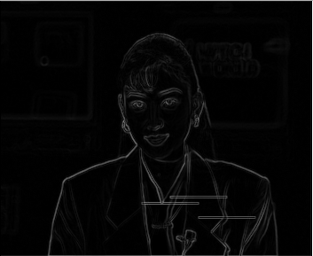
To simulate the effect of cache misalignment on the Sobel application, force the alignment on addresses that are multiples of “3”. If you are unlucky enough, several buffers will be allocated in ranges of memory cached in a single line of cache, and corrupted lines will appear in the result produced by the algorithm. The following figure gives an example of corrupted output:
Finally, all techniques presented in the CPU tutorials, such as the memory footprint reduction or the pipelining techniques can successfully be used to seamlessly improve the performance of an application on a multicore DSP.